Crane Beam Design Guide: Steel Structure Loads, Span & Cost
Crane beam design guide for steel structures. Learn wheel loads, impact factors, span design, connection details, and cost control for industrial crane systems.
Crane beams are among the most critical structural elements in industrial steel buildings. A poorly designed crane beam can lead to excessive deflection, premature fatigue cracking, or catastrophic failure — while an over-designed one wastes steel and inflates project cost.
This technical guide covers everything engineers and buyers need to know about steel structure crane load design, from crane types and wheel load calculation to span optimization, connection details, and cost control.
Types of Cranes in Steel Structures
Before designing a crane beam, you must understand the crane type it will support. Each type generates different load patterns and demands different beam configurations.
Overhead Cranes (Bridge Cranes)
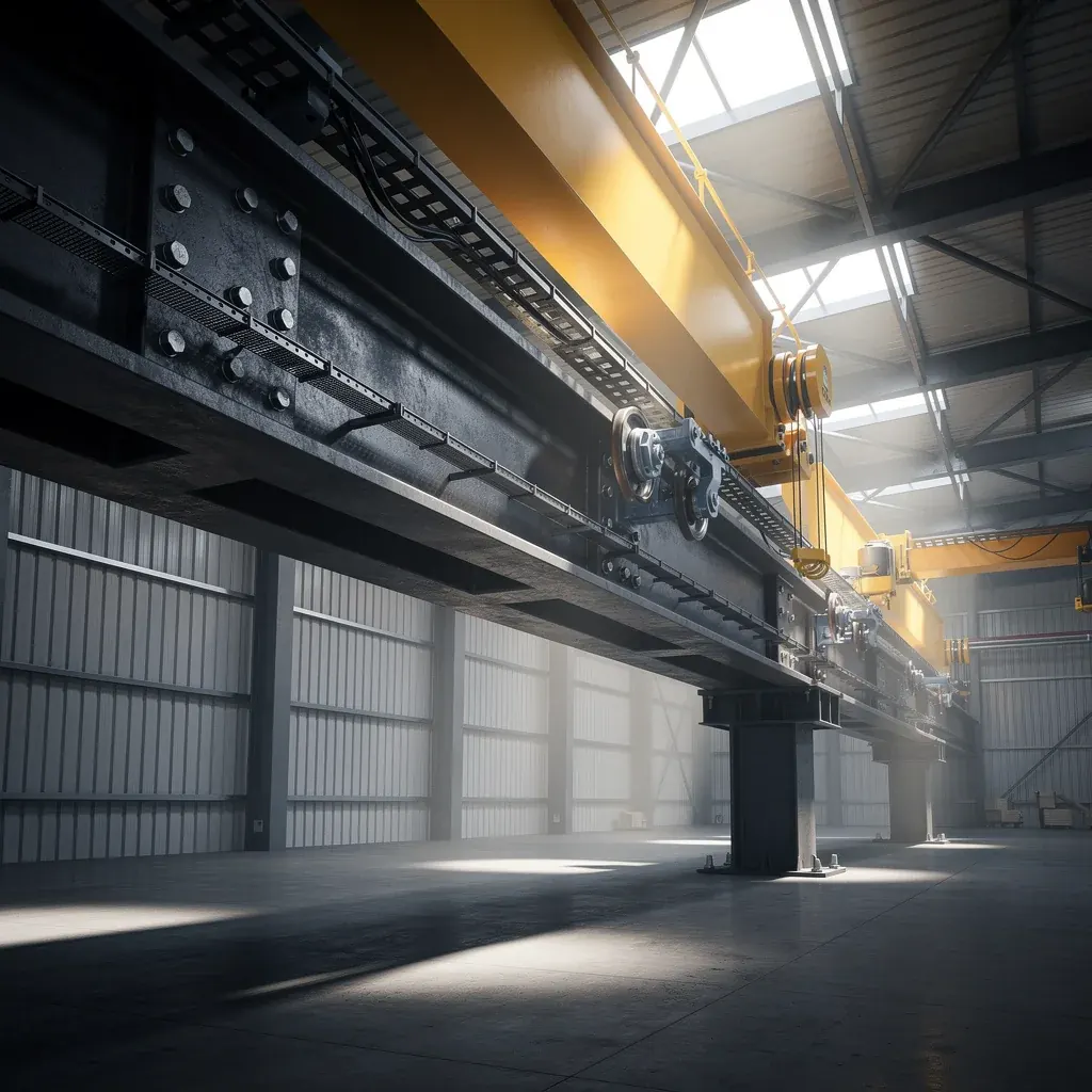
Overhead cranes are the most common industrial crane type. They run on two parallel runway beams along the length of the building. The bridge spans between the runways and carries a hoist trolley.
- Capacity range: 1 ton to 500+ tons
- Runway beam type: Welded I-section or hot-rolled H-section
- Load characteristic: Moving concentrated wheel loads along the beam length
- Typical application: Steel mills, heavy fabrication shops, foundries
Jib Cranes
Jib cranes consist of a vertical mast with a horizontal cantilever arm. They are mounted to a building column or a freestanding foundation.
- Capacity range: 0.25 ton to 10 tons
- Load characteristic: Concentrated moment and torsion at the support column
- Typical application: Workstations, loading docks, assembly lines
Monorail Cranes
Monorail cranes use a single beam as both the runway and the bridge. A hoist trolley runs along the bottom flange of the beam.
- Capacity range: 0.5 ton to 20 tons
- Load characteristic: Point load moving along a fixed path, often curved
- Typical application: Paint lines, assembly conveyors, material transfer
| Crane Type | Capacity Range | Beam Type | Load Pattern | Relative Cost |
|---|---|---|---|---|
| Overhead | 1–500+ t | Runway beam (I/H) | Moving wheel loads | High |
| Jib | 0.25–10 t | Cantilever arm | Moment + torsion | Medium |
| Monorail | 0.5–20 t | Single beam (I) | Point load along path | Low–Medium |
Crane Load Calculation
Accurate crane beam design starts with correct load determination. The primary loads on a crane runway beam come from the crane wheels.
Wheel Loads
The wheel load is the maximum load transmitted by a single crane wheel to the runway beam. For a bridge crane with four wheels:
Maximum wheel load = (Crane dead weight + Hoist + Rated load) × (Distance from far side / Total span) / Number of wheels per side
Key factors affecting wheel load:
- Rated capacity (lift load)
- Crane self-weight (bridge + trolley + hoist)
- Trolley position (worst case = trolley at minimum hook approach)
- Number of wheels per crane side (2, 4, or 8 wheels)
Impact Factor
Crane operations generate dynamic effects beyond the static load. Design codes require an impact factor to account for lifting, lowering, and sudden stops.
| Crane Type | Impact Factor (Vertical) | Lateral Force | Longitudinal Force |
|---|---|---|---|
| Monorail | 1.25 | 20% of wheel load | 10% of max wheel load |
| Cab-operated overhead | 1.25 | 10% of wheel load | 10% of max wheel load |
| Pendant-operated overhead | 1.10 | 10% of wheel load | 10% of max wheel load |
| Jib crane | 1.25 | Per manufacturer | — |
Lateral and Longitudinal Loads
- Lateral force: Caused by crane trolley movement and bridge skewing. Typically 10–20% of the maximum wheel load, applied perpendicular to the runway.
- Longitudinal force: Caused by crane braking. Typically 10% of the maximum wheel load, applied along the runway beam axis.
Span Design for Crane Beams
The span of a crane runway beam is the distance between support columns. Proper span design balances structural efficiency, crane performance, and cost.
Recommended Span Ranges
| Crane Capacity | Recommended Beam Span | Typical Section Height |
|---|---|---|
| Up to 10 t | 6–9 m | 400–600 mm |
| 10–20 t | 6–9 m | 500–700 mm |
| 20–50 t | 9–12 m | 700–1000 mm |
| 50–100 t | 9–12 m | 900–1200 mm |
| 100+ t | 6–9 m (heavy section) | 1200+ mm |
Deflection Limits
Deflection is often the governing design criterion for crane beams — not strength. Excessive deflection causes crane rail wear, trolley tracking problems, and operator discomfort.
| Crane Class (AISC / CMAA) | Allowable Vertical Deflection |
|---|---|
| Class A (Standby) | L/600 |
| Class B (Light service) | L/600 |
| Class C (Moderate) | L/800 |
| Class D (Heavy) | L/800 |
| Class E (Severe) | L/1000 |
| Class F (Continuous severe) | L/1000 |
Fatigue Considerations
For cranes in Class D or above (frequent operation), fatigue design is mandatory. Fatigue-critical zones include:
- Welded connections at rail clips
- Web-to-flange welds at maximum shear locations
- Bracket connections to columns
- Coping and notching details
Connection Details
Crane beam connections transfer vertical, lateral, and longitudinal forces from the beam to the building frame. Poor connection design is the leading cause of crane beam failure.
Beam-to-Column Connection
- Vertical support: A bearing stiffener or cap plate transfers the vertical reaction to the column cap or bracket.
- Lateral support: A lateral brace (angle or plate) connects the top flange to the building frame, resisting lateral crane forces.
- Longitudinal support: Slotted holes allow thermal expansion while resisting braking forces.
Rail Connection
Crane rails are typically attached to the beam top flange using one of these methods:
| Rail Attachment Method | Advantage | Disadvantage | Best For |
|---|---|---|---|
| Hook bolts | Simple, adjustable | Lower capacity | Light cranes (<10 t) |
| Clips (rail clamps) | Standard, reliable | Requires periodic re-torquing | Medium cranes (10–50 t) |
| Direct welding | Rigid | Rail cannot move, stress concentration | Rare — not recommended |
| Rail pads + clips | Reduces impact, absorbs vibration | Higher cost | Heavy cranes (50+ t) |
End Stops and Bumpers
End stops at the runway terminations absorb the kinetic energy of a moving crane. Design the end stop connection for the bumper impact force, not just the static crane weight.
Cost Factors in Crane Beam Design
Crane beam cost is driven by steel tonnage, fabrication complexity, and connection detailing. Understanding these cost drivers helps optimize the design.
Steel Tonnage
Crane beams typically account for 15–25% of the total steel tonnage in an industrial building with overhead cranes. For heavy-duty cranes (50+ tons), this can rise to 30–35%.
Fabrication Complexity
- Welded I-sections: Cost-effective for standard sizes, but requires careful welding quality control.
- Hot-rolled H-sections: Lower fabrication cost, but limited to standard sizes — may be over-designed for heavy loads.
- Built-up box sections: Highest cost, used for very heavy cranes or long spans where torsion is a concern.
Cost Optimization Tips
- Use standard hot-rolled sections whenever they meet the design requirements — fabrication cost is 20–30% lower than welded sections.
- Optimize column spacing to match recommended beam spans — avoid spans just over 9m that force a heavier section.
- Minimize stiffeners and brackets — every additional stiffener adds fabrication labor cost.
- Consider a continuous runway over multiple spans to reduce peak moments — but ensure proper expansion joints.
- Coordinate rail size early — oversized rails require wider flanges, increasing beam cost.
Common Crane Beam Design Mistakes
1. Ignoring Fatigue for Heavy-Duty Cranes
Many designers apply static load design only, ignoring fatigue for cranes operating more than 100,000 cycles. This leads to crack initiation at welded details within 5–10 years.
2. Underestimating Lateral Loads
Lateral forces from trolley braking and bridge skewing are often underestimated. This causes excessive lateral deflection, rail misalignment, and accelerated wheel wear.
3. Inadequate Stiffener Design
Bearing stiffeners at support points and intermediate stiffeners in high-shear zones must be properly sized. Undersized stiffeners cause web buckling and local failure.
4. Poor Rail Alignment Tolerance
If the beam fabrication tolerance does not match the rail alignment requirement, the crane will bind and wear prematurely. Specify camber and tolerance requirements clearly in the fabrication drawings.
5. Neglecting Maintenance Access
Crane beams require periodic inspection of rails, clips, and connections. Designs without walkways or safe access platforms lead to deferred maintenance and hidden deterioration.

Design Workflow Summary
Follow this step-by-step workflow for a reliable crane beam design:
- Define crane specifications — capacity, span, class, wheel base, and wheel loads from the manufacturer.
- Determine loads — apply impact, lateral, and longitudinal factors per the governing code.
- Select beam span — match column spacing to recommended span ranges.
- Choose section type — hot-rolled, welded I, or box section based on load and span.
- Check strength — bending, shear, and local buckling per AISC 360 or GB 50017.
- Check deflection — verify vertical and lateral deflection within code limits.
- Check fatigue — for Class D and above, verify stress ranges at critical details.
- Design connections — beam-to-column, rail attachment, and end stops.
- Specify fabrication tolerance — camber, straightness, and rail alignment.
- Plan maintenance access — walkways, ladders, and inspection platforms.
FAQ
Q: What is the standard impact factor for overhead crane beam design?
A: For cab-operated overhead cranes, the vertical impact factor is typically 1.25 (25% increase over static load). For pendant-operated cranes, it is 1.10. Always confirm with the crane manufacturer and applicable code (AISC, GB, or Eurocode).
Q: How do I calculate the maximum wheel load for a bridge crane?
A: The maximum wheel load occurs when the fully loaded trolley is at its closest approach to one runway. It equals (crane dead weight + rated load) distributed to the wheels on that side, with the trolley position maximizing the load. The crane manufacturer provides this value in the load chart.
Q: What is the maximum recommended span for a crane runway beam?
A: For most overhead cranes up to 50 tons, the recommended span is 6–9 meters. For heavier cranes or special configurations, spans up to 12 meters are possible but require significantly heavier sections. Beyond 12 meters, consider a box section or intermediate support.
Q: Should I use welded or bolted connections for crane beams?
A: Shop connections are typically welded for strength and rigidity. Field connections should be bolted to accommodate erection tolerances and future maintenance. High-strength bolts (ASTM A325 or A490 / Grade 10.9) are standard for crane beam connections.
Q: How often should crane beams be inspected?
A: Per CMAA and OSHA guidelines, crane runways should receive a visual inspection at least monthly, with a detailed structural inspection annually. Critical welded connections should be inspected using magnetic particle or ultrasonic testing every 2–5 years depending on crane usage class.
Need Expert Help with Your Crane Beam Design?
Designing crane beams requires specialized engineering knowledge and precise load calculations. At Laotie Steel, our engineering team has designed crane runway systems for capacities from 2 tons to 200 tons, across workshops in over 40 countries.
Whether you need a single jib crane beam or a complete heavy-duty runway system, we can help you optimize the design for safety, performance, and cost.
Contact us today for a free crane beam design consultation and quotation. Share your crane specifications and building layout — we will deliver a detailed design proposal within 48 hours.
Related Articles
Steel Structure Wind Load Calculation: Complete Design Guide
Learn wind load calculation for steel structures. Compare ASCE 7, Eurocode 1, GB 50009 and AS/NZS 1170. Includes exposure categories, gust factors, and design examples.
Steel Structure Corrosion Protection: C1 to C5 Guide
Complete guide to steel structure corrosion protection. Learn ISO 12944 C1-C5 classification, coating system selection, galvanized vs painted vs duplex, and cost comparison.
Need a Steel Structure?
Get a free quote from our engineering team. We respond within 2 hours.
Request a QuoteStay Updated
Get steel structure tips, cost guides, and industry insights delivered to your inbox.
No spam. Unsubscribe anytime.